9 results (0,14316 seconds)

Brand

Merchant

Price (EUR)

Reset filter

Products
From
Shops

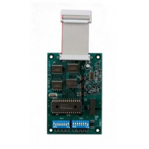
Ziton 9-30437 APIC Card - Ziton Protocol

Ziton ZP3AB-NET1 Network Board Optional Facility Card

Ziton ZP3AB-NET1 Network Board Optional Facility Card

Ziton ZP3AB-NET1 Network Board Optional Facility CardThe ZP3AB-NET1 enables ZP3 control panels to be connected together to form networks. The interface card is attached directly onto the ZP3 main control board inside the panel enclosure. Up to 64 standalone control panels can be linked to form the ZP network allowing the integration of over 32 000 system devices.Networks can be designed as peer to peer systems where all control panels are connected to form a single coordinated fire detection and alarm system. Each panel controls its own devices and displays its own system information but is capable of cross panel cause and effect operation. The ZP3AB-NET1 network board also enables hierarchical networks to be easily configured where one or more control panels can be assigned as masters displaying complete system status.RS485 protocolCommunication between ZP3 fire alarm panels operates by RS485 protocol over twisted screened pair wiring. Total cable length throughout the network can be up to a maximum of 2 kilometres. On larger sites where wiring runs to remote systems may exceed this maximum cable lengths can be extended by the addition of RS485 booster units or optical fibre connection.Designed to provide flexible system configuration system wiring can be daisy chained or teed off with spurs. Network connections are in data quality cable with a minimum core diametre of 0.5 mm. Jumper terminating switches are provided on all network interface boards which are set at the system commissioning stage.Cost effective optionsThe ZP3AB-NET1 network board is part of the range of optional facility boards which can be added cost effectively to any ZP3 control panel in order to provide extra facilities that may not be a requirement of every system.Housed within the ZP3 panel options can simply be added during panel manufacture to meet particular specifications or subsequently fitted on site should a particular requirement become necessary during the life of the system.Key FeaturesUp to 64 panel networkingHoused inside main panel enclosureComplete cross panel communicationsInter panel cause and effect operation

GBP 277.07
1

Ziton Z-PCRS485-2 RS485 Interface Card for PC Connection to ZP3 Network CP-132UL-I-V2

Ziton ZP3AB-RS232 Serial Communications Optional Facility Card

Ziton ZP3AB-SCB-R Serial Control Bus Interface

Ziton 71601 ZP3 Repeater Panel

Ziton 71601 ZP3 Repeater Panel

Ziton 71601 ZP3 Repeater PanelDesigned to match the ZP3 main control panel the ZP3-RDU remote display is an attractive low profile unit providing repeat indication and system control at a location remote from the main control panel position. Housed in a small slim enclosure the remote unit has a fascia design and layout in matching style to ZP3 control equipment. Up to 32 remote units can be connected to any central panel.The unit features zonal designation for up to 50 zones a 4 row 160 character back lit liquid crystal display and an at a glance system status LED matrix. Controls are provided for accept reset silence and sound alarms. A restore disabled alarms facility re-enables previously disabled alarm sounders immediately should the need for an evacuation arise.The unit is driven from an optional serial driver card added to the main board within the ZP3 panel enclosure. Wiring to the main control panel is by serial link screened twisted pair which can be daisy chained teed off or spurred. The total wiring length of all remote display units connected to a main control panel can be up to two kilometres. The ZP3-RDUB1 can either be powered directly from the main panel 24 VDC or by a remote power supply unit. A version featuring a stainless-steel enclosure is also available.Control keys are provided to select listings of current fires faults and disablements for display. Initial information is displayed by zone with a further facility to display point addresses within the displayed zone. Operating as an indicator panel only in its normal mode the ZP3-RDUB1 system control functions are accessed by means of a security key switch. Internal switches are provided to configure the unit to operate as an indicator only with no control facilities with controls by key access or with control functions enabled on a permanent basis.Key FeaturesRemote control and indicationUp to 32 remote units connected to each main panel4 row 160 character LCDReplicates main panel fasciaRestore disabled sounders facility

GBP 887.51
1

Ziton Stainless Steel Repeater Panel 24V LCD amp controls 130101

Ziton Stainless Steel Repeater Panel 24V LCD amp controls 130101

ZitonStainless Steel Repeater Panel 24V LCD controlsDesigned to match the ZP3 main control panel the ZP3-RDU remote display is an attractive low profile unit providing repeat indication and system control at a location remote from the main control panel position. Housed in a small slim enclosure the remote unit has a fascia design and layout in matching style to ZP3 control equipment. Up to 32 remote units can be connected to any central panel.The unit features zonal designation for up to 50 zones a 4 row 160 character back lit liquid crystal display and an at a glance system status LED matrix. Controls are provided for accept reset silence and sound alarms. A restore disabled alarms facility re-enables previously disabled alarm sounders immediately should the need for an evacuation arise.Displays both zone and address informationControl keys are provided to select listings of current fires faults and disablements for display. Initial information is displayed by zone with a further facility to display point addresses within the displayed zone. Operating as an indicator panel only in its normal mode the ZP3-RDUB1 system control functions are accessed by means of a security key switch. Internal switches are provided to configure the unit to operate as an indicator only with no control facilities with controls by key access or with control functions enabled on a permanent basis.Serial link connectionThe unit is driven from an optional serial driver card added to the main board within the ZP3 panel enclosure. Wiring to the main control panel is by serial link screened twisted pair which can be daisy chained teed off or spurred. The total wiring length of all remote display units connected to a main control panel can be up to two kilometres.The ZP3-RDUB1 can either be powered directly from the main panel 24 VDC or by a remote power supply unit. A version featuring a stainless steel enclosure is also available.Key FeaturesRemote control and indicationUp to 32 remote units connected to each main panel4 row 160 character LCDReplicates main panel fasciaRestore disabled sounders facility

GBP 1276.07
1

Ziton ZP3AB-NLM3 Class-A Network Loop Module

Ziton ZP3AB-NLM3 Class-A Network Loop Module

Ziton ZP3AB-NLM3 Class-A Network Loop ModuleThe ZP3AB-NLM network loop module enables individual ZP3 control panels to be connected in a peer to peer secure loop network. If there is an open or short circuit present on the network wiring the NLMs determine where the fault lies isolate the faulty section of wiring and maintain full loop integrity.Total cable length throughout the network can be up to a maximum of two kilometres and may be extended by setting designated NLM modules as booster units contact Ziton technical support department for full details. Communication between loop modules operates by RS485 protocol over screened twisted pair wiring.Unique address on the network loopZP3AB-NLM3 modules connect to ZP3 control panels via a ZP3AB-NET1 card and are designed to fit onto an auxiliary chassis inside each control panel or auxiliary equipment cabinet. Each ZP3 control panel is connected to the loop network through an ZP3AB-NLM3 module. All modules incorporate switch settings enabling them to be assigned a unique loop address. An output fault signal is provided by a volt free changeover relay with contacts rated at 1A at 230VDC30VAC.Diagnostic and system indicationIn each network loop one module must be set to address 1 and designated as the master. This device manages the healing sequence and monitors loop integrity. All other modules are connected to the network loop in slave mode.In slave mode modules can operate in multiple modesBoost - serving as an interconnection between panels at distances over 1000 metresHealing establishing the condition of the loop and isolating sections if necessaryRecovered normal condition after a section isolationDiagnostic system interrogation to establish the location of a break in the loop wiringIn addition to indications of data being transmitted and received from each port LED indicators are also provided for System OK Loop Fault Loop Open and Data Error.Key FeaturesProvides a secure loop networkEnhanced LED diagnosticsBoost mode for long cable runsPropagation time periods for third party equipment operationCommunications screen isolation between input and output channels

GBP 277.06
1